Show Nodes v2 Hardware Information and Instructions
Components
- Raspberry Pi 2 Model B or Raspberry Pi 3 Model B (www.raspberrypi.org)
- PiFace Digital 2 Revision 2 (piface.org.uk)
- SanDisk MicroUSB Card 16gb
Recommended Power Supplies
Primary evaluation criteria – Must supply at least 2 Amps of +5v to the Raspberry Pi and the appropriate voltage needs for your props. We typically use the 24V version and use a step down converter as necessary for 12V props.
- 24/5V Version – PSS0524-100 – RHINO switching power supply, 24 VDC (adjustable), 5 VDC output, 100W, 120/240 VAC or 125-375 VDC nominal input, 1-phase, aluminum housing, screw terminals.
12/5V Version – RT-125A – 131 Watt AC to DC Triple Output Power Supply +5V/12A +12V/5.5A -5V/1ANo longer recommended because it requires a minimum level of amperage pull to turn on.
Additional options for power include getting a single voltage power supply and down-converting to 5V for the Raspberry Pi or even just getting a separate power supply for both voltages. You need to make sure your down-converter can handle at least 2 amps.
I have used the following step-down converters:
- DROK® 5 Pcs DC Step Down Variable Voltage Regulator 36V to 24V 12V 5V 3.3V 3V Buck Converter Electronic Volt Stabilizer Car Battery Adjustable Regulated Power Supply DIY Voltage Transformer Module
- DROK LM2596 Analog Control Buck Converter DC-DC 4-32V to 1.25-30V Step-down Regulator Module 24V 12V to 5V 3A Power Inverter Volt Stabilizer with Red LED Display
And power supplies at 12 volt:
PiFace Digital 2 Jumpers
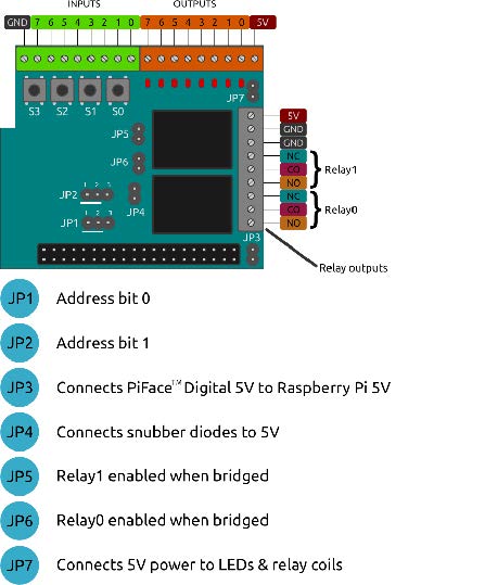
The PiFace Digital 2 is delivered with all jumpers in place. This allows both us to test prior to shipping and you to test and and learn prior to placing into service. Normally we setup the PiFace to supply the primary power to the Raspberry Pi and Inputs. Jumper 3 determines whether when the power is supplied to PiFace Power Inputs. This jumper (Jumper 3) is very important, it literally means you can only plug in power to either the Raspberry Pi USB power port OR the PiFace. Connecting power to both the 5V in on the PiFace and the Raspberry Pi can easily cause an electrical problem and blow out one or both of the boards. This will be corrected in V3 of the ShowNodes hardware.
Once you get ready to place the unit into service and hook up something other than 5V, you will need to change the Jumpers. As soon as you move higher than 5V you will need to remove Jumper 4 (JP4). This Jumper connects a snubber diodes to prevent back voltage from the Outputs. Just remember, more than 5V remove Jumper 4 (JP4).
If you are not using the Relay 0 or Relay 1 you can disconnect them by removing either JP6 for Relay 0 or JP5 for Relay 1. We would also suggest removing JP7 if you are not using the relays. This jumper is for providing the power for lighting the LEDs and turning on/off the relays.
Our normal production setup of the jumpers is to have JP1 and JP2 on pins 1/2. JP4, JP5, JP6, and JP7 removed. This allows us to use multiple DC voltage levels on the outputs and doesn’t have the relays clicking for the first two outputs.
Wiring
Output
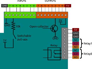
If using one of our recommended power supplies, you will run +5 volts to the +5 terminal in the black terminal connector of the PiFace. Run the 5V ground to one of the two GND terminals next to it. DO NOT connect USB power to the Raspberry Pi power port. To connect 24/12V Pneumatic Valves or other 24/12V props, connect the positive side of the power supply terminal to the positive side of the valve and then connect the negative side of the valve to the Output on the PiFace in this manner:
Diode Standard 1000V (1kV) 1A Through Hole DO-41
Input
The input terminals are basic contact closure inputs not for power driving inputs. They are internally pulled up to approximately 4.5 volts. To connect a standard switch you can simply connect one wire to the input pin and the other wire to the ground. To connect sensors and other non-5 volt input devices, you will need a Voltage Divider or Opto-Isolator circuit.